




Braided Hose Sample Validation for PC Liquid Cooling Loops
INDUSTRY APPLICATIONS · RESRUB
A PC cooling loop joins a water block, radiator, pump and reservoir within limited case space. A braid-covered hose can make the build look finished, but the inner tube and its fittings determine whether the proposed assembly works with a specified coolant. This article follows the sample through eight practical decisions, from route photo to signed-off specification.
The accompanying images are illustrative design visuals supplied for this article, not photographs of a RESRUB test or evidence of a specific product specification. Use the PC liquid cooling tube solution for the broader product context.
1. Start with the complete PC cooling loop
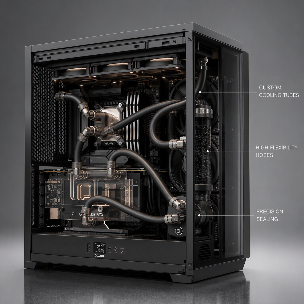
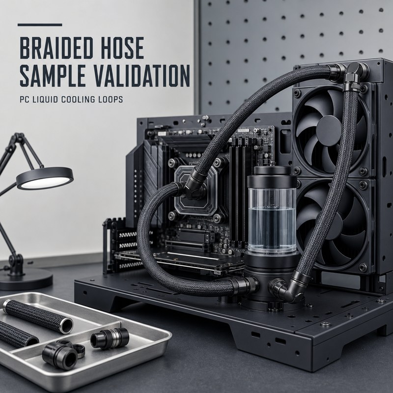
The overview visual places braided hoses between a water block, radiator and reservoir. For a real project, start from a case drawing or annotated build photo. Identify the pump, every port and the intended order of connections before asking for a cut length.
- Send a route sketch with port positions, fitting part numbers and the available space.
- State whether the hose is a cut tube or a preassembled hose-and-fitting unit.
- Record coolant name, cleaning process and target service conditions for the proposed sample.
Do not assume a pictured assembly represents a tested configuration. The purchaser and fitting supplier should agree the exact connection geometry and test acceptance criteria.
2. Trace the bend path and clearance
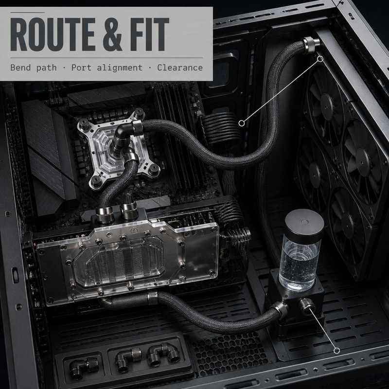
The route-and-fit visual calls attention to the bends around the CPU/GPU blocks and the radiator ports. In the actual case, check the route with installed fittings and the case panel closed. A tight curve near a fitting is different from a free bend in the middle of the hose.
- Check for pinching, rubbing, fan interference and obstruction during service access.
- Measure the tightest installed curve and confirm the candidate tube does not kink or flatten.
- Leave enough slack for assembly without introducing unwanted contact or twisting.
No universal bend radius is supplied here: it depends on the actual tube construction, diameter and fitting. Document the route with photographs at the approved build state.
3. Measure the tube and fitting interface
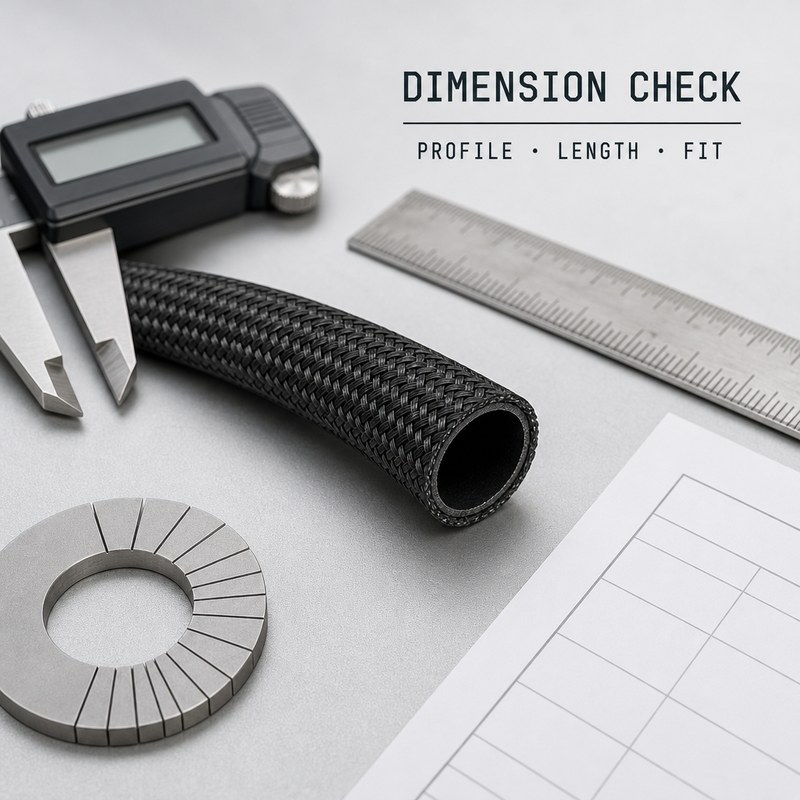
The dimension image shows a hose, caliper, ruler and worksheet. Translate that visual into a revision-controlled drawing with inner diameter, outer diameter including braid, wall, cut length and tolerances. A nominal ID by itself cannot prove a leak-free fit.
- Measure several positions and orientations of the supplied sample.
- Trial-fit the production-intent fitting and record insertion depth and retention method.
- Verify finished length after assembly rather than relying on an uninstalled straight measurement.
Agree what dimensions are critical to seal quality and what inspection method will be used for repeat orders.
4. Identify the inner tube separately from the outer braid
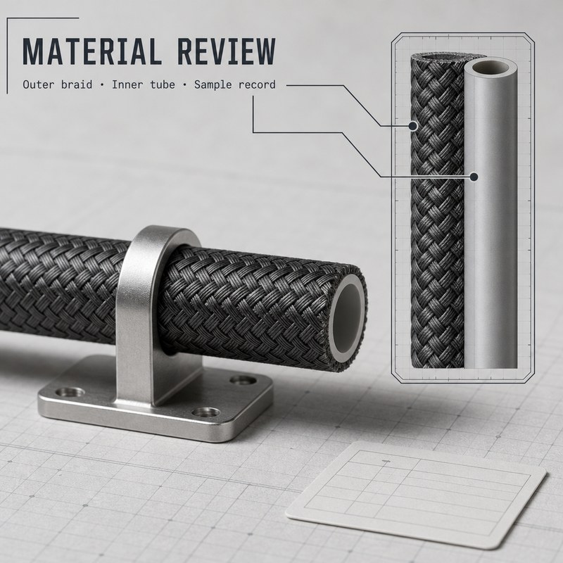
The material-review visual separates the visible braid from the fluid-contact tube. Ask which layer touches the coolant and whether the outer braid is cosmetic, protective or part of a documented reinforcement construction. Do not infer a pressure rating from the weave.
- Request the exact inner-tube compound and braid material for this model.
- Inspect cut ends for loose fibers, damage and braid movement under the fitting.
- Confirm whether the proposed inner tube is silicone or EPDM and review its suitability for the actual coolant.
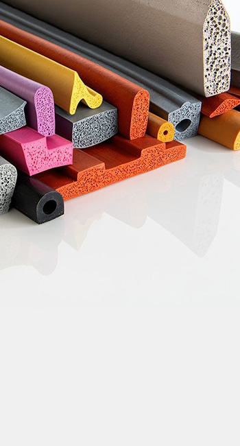
RESRUB offers silicone and EPDM tubing and custom development; material selection needs model-specific evidence. See materials and process capabilities for supplier context.
5. Test against the named coolant, not a generic fluid
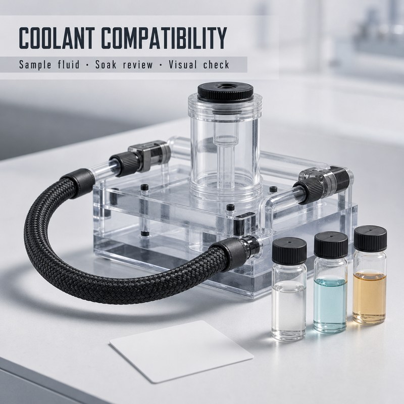
The coolant-compatibility scene depicts sample fluids and a hose loop. Actual approval needs the coolant trade name or formulation, concentration, additives, cleaning agent and exposure conditions. If the formula changes, revisit the compatibility decision.
- Agree the sample soak or circulation method and the pass/fail criteria in advance.
- Inspect fluid discoloration, residue and changes in the tube after exposure.
- Record dimensional, hardness or other agreed property changes when relevant.
An illustrative fluid vial is not a compatibility report. Request results for the exact proposed hose compound and the intended fluid system.
6. Check the assembled joints for leakage
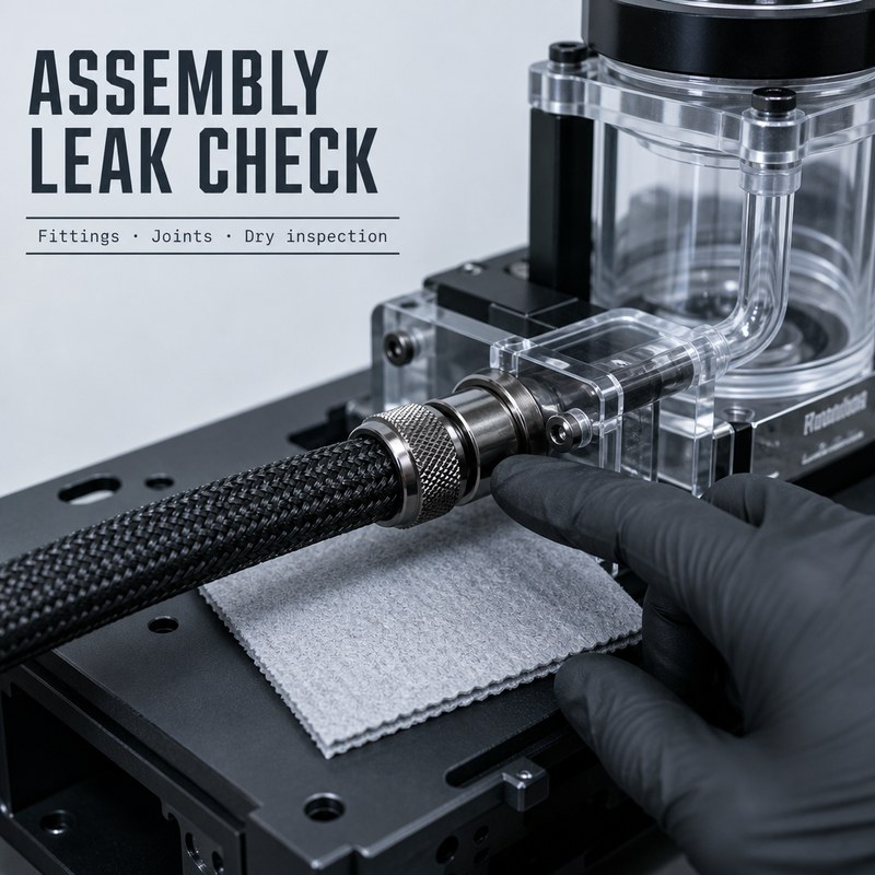
The assembly-leak image focuses on the interface between braided hose and fitting. A dry wipe near a joint is useful for visual inspection, but the full test procedure, duration and acceptance threshold must be defined for the buyer’s loop.
- Test the production-style fittings, clamps and hose lengths as one assembly.
- Inspect every connection and the hose body under agreed static and operating conditions.
- Repeat inspection after routing, service movement and any agreed temperature cycling.
Keep the test record tied to the sample identifier and drawing revision. Neither this image nor a clean-looking connection constitutes a leak-test certificate.
7. Approve one traceable sample revision
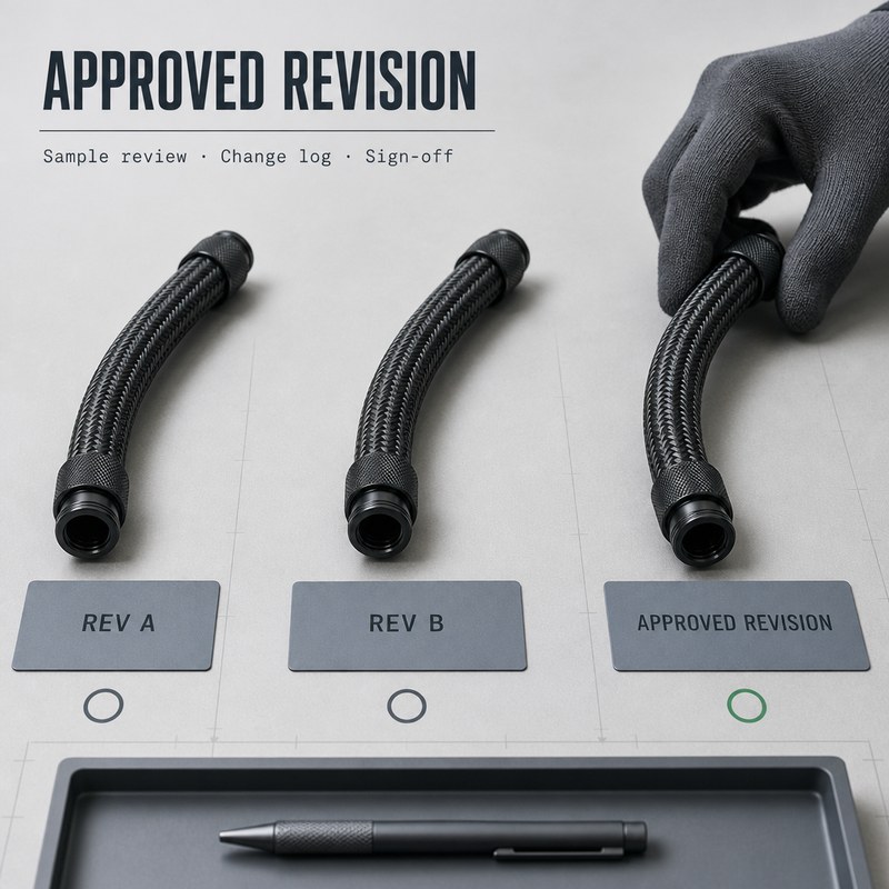
The revision image contrasts three hose samples and an approval marker. Keep the change log practical: tube compound, braid, ID/OD, cut length, fitting and coolant are each capable of affecting a previous approval.
- Label samples and reports with the same drawing revision.
- Retest affected criteria after changing the tube, fitting, routing or coolant.
- Retain a signed-off sample and an agreed inspection sheet for repeat production.
An approved photograph is not a substitute for the actual revision-controlled drawing and acceptance record.
8. Hand over a concise OEM sample package
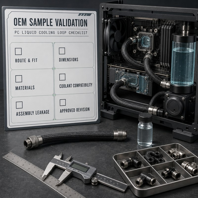
The closing checklist visual brings route, dimensions, materials, coolant, leakage and approval together. Send the supplier one package: drawing, annotated build photo, fitting identifiers, fluid details, target quantity and the tests you expect on the first sample.
- Ask for proposed construction, sample lead time and required evidence.
- State which measurements and assembly checks decide acceptance.
- Freeze the approved revision before ordering production lengths.
RESRUB offers free design support and one-piece minimum-order sampling for suitable custom projects; confirm tooling feasibility, price and timing for this design with the custom solution team.
Sample approval record: minimum fields
| Item | Record to retain | Acceptance decision |
|---|---|---|
| Route & fit | Case photo, fitting IDs, bend and clearance notes | Build fits without kinks or interference |
| Dimensions | Dated drawing and measured sample results | Within agreed drawing tolerances |
| Material & coolant | Tube/braid identification and specific fluid test | Meets agreed exposure criteria |
| Joint integrity | Assembly method and leakage-test record | Meets project leakage criteria |
| Revision | Approved sample ID and change log | Same controlled configuration for production |
Frequently asked questions
Does a visible braid prove that the hose is high-pressure rated?
No. The specific tube construction, fittings and test report must support any pressure rating for the assembled system.
Can silicone and EPDM be substituted without retesting?
No. Evaluate the exact compound against the named coolant and the intended temperature and service conditions.
Are the pictures actual product test results?
No. They illustrate validation steps and cannot replace a drawing, material data or sample test record.
For general pressure, bend and fitting selection, see the braided hose assembly guide. Explore other Industry Applications articles.